Short, useful reading for teams selecting, operating and maintaining telescopic foundation drilling bars.
The blog connects equipment decisions with the realities of ground, tools, logistics and service. Each article is written as a practical reference for the next project conversation.
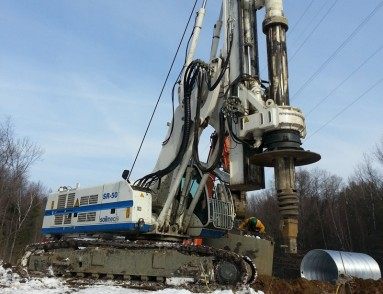
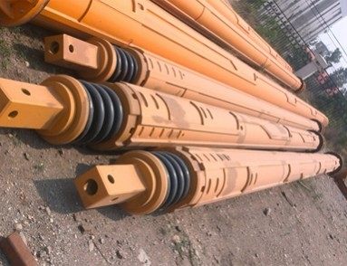
A Kelly bar is part of the rotary drilling system. The first step is to record the rig model, drive interface, available torque, crowd force, mast height and the tool connection. Those details define the working envelope. A bar can have an impressive nominal depth and still be unsuitable if its drive box, section length or handling weight does not fit the machine.
Kelly bars work through repeated cycles of torque, crowd, extension, retraction and handling. Wear rarely appears as one dramatic event; it develops through small changes in contact, alignment or surface condition. A short routine at the start and end of a shift gives the crew a chance to notice those changes while the equipment is still easy to service.
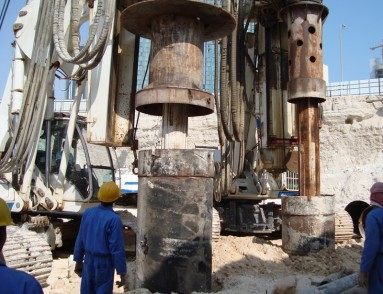
A drilling bar experiences the ground through the tool, not through the soil description alone. A layer of dense gravel can create intermittent impact and torque spikes, while cohesive clay may increase extraction resistance. Weathered rock can combine abrasion with vibration. Thinking in terms of load history makes it easier to connect field behavior with bar selection and inspection.
When a bar question appears on site, begin with the rig, tool and ground. Those three inputs explain most of the decisions around section count, working depth, engagement principle and wear monitoring. The articles below expand that checklist with examples that can be shared between engineering, workshop and drilling crews.
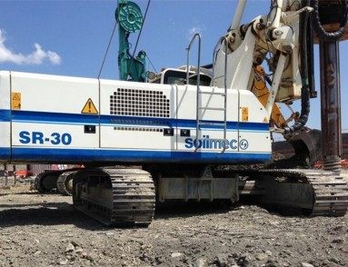
For model-specific information, browse the Soilmec Kelly bar range. For a structured request, use the quotation page and include the details described in the selection article.
Project reference notes
Foundation Drilling Blog | Kelly Bar Systems is intended to be used as a working reference alongside the rig documentation and the approved project drawing. The useful decision is always specific to the machine, tool and ground: check the rotary interface, available torque, crowd behavior, target depth, section overlap and handling space before a final configuration is released. These details also help the field team understand why a particular bar arrangement was selected.
Keep the page available during quotation, commissioning and service review. During installation, confirm the section order and connection fit at low speed. During production, record ground changes, tool changes and any new sound or movement. During demobilization, clean the contact areas, protect the connections and carry the inspection record with the section marks. That small information loop makes the next decision faster and keeps the equipment history useful across projects.
For procurement and site planning, identify the bar by its complete model and section arrangement rather than by a shortened label alone. Confirm how it will be packed, lifted, stored and connected to the selected tool. If the project involves more than one rig, compare the interfaces before standardizing the order. Clear information at this stage reduces field modifications, protects the schedule and gives the service team a reliable starting point when the equipment returns from the job.